A Detailed Account of Building my WorkshopThis article is not so much about how I built my new workshop as it is about the thought process and planning that I went through and the decisions I had to make along the way. First and foremost, I realized that building a woodworking shop is surely a once in a lifetime project. I’m an engineer by training and have spent my career involved with large and complex projects. I decided to approach this project the same as I would any other engineering project – with careful planning and attention to detail. Most importantly, I knew that the planning and design phases are critical to the project’s ultimate success. From the time I made the decision to build the shop until I started my first woodworking project in my new shop was nearly two years! It might not have taken that long if I was not spending 60 hours a week at my day job which involves a great deal of travel. But I was determined not to rush the process. This was going to be the biggest woodworking project of my life and I was going to take my time, plan carefully, and enjoy the process. Some of you reading this may be wondering about the financial aspect of doing something like this. You might be thinking that I’m a rich man with money to burn. I can assure you that’s not the case, but understanding the project’s realistic cost and deciding on a budget is the first thing that must be tackled. I’m at the age where many of my friends are buying luxury cars as a reward for working hard their entire career. I’m very happy driving my old pickup truck, so the price of a new luxury car seemed like a good financial benchmark. I reasoned that I could, if I really wanted to, find a way to pay for a new car. But unlike a car, my shop would not start depreciating in value as soon as I drove it off the lot! I also wanted the shop to add to my property value, so it was important to design the building as much for the next guy as for myself. This theme underscored much of the design process and caused my to ask myself questions like, if the next guy’s hobby is antique cars, will this building’s design turn him away? Where to put the building is the first major decision I had to make. I have about four acres of property, but in spite of that, my choices were somewhat limited. Many factors had to be taken into consideration including local zoning laws, the location of overhead power lines, the proximity of the site to power, and most importantly, I wanted a shop location that would make it very easy to move material and tools in and out of the building. As an engineer I’m well acquainted with many different computer drafting and design programs. I chose to create a scale model of my property using a program called Visio and to use the model to work through the various options. But it is certainly not necessary to use a computer for this step. Pencil and paper along with an architect’s ruler are really all that is necessary. In my case, I dug out my property survey from the safety deposit box and started by creating a border that represented the property lines. This does not have to be precise but does need to be reasonably accurate and must also reflect any unusual angles.
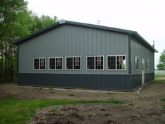
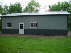
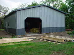
Next I used the survey information to create scale models of the existing buildings and my driveway. These were placed in the model in their correct relative location. Finally I was able to create models of various shop footprints and place the new footprints virtually anywhere I wanted with any orientation. This is more complicated in the telling than in the doing. Visio is a very easy program to master and much, much simpler to use than most computer aided drafting programs. Unlike many of the steps involved with a project of this type, it would be impossible to recover from a mistake at this stage of the process. Once the building is up, it is too late to change where you put it! So, I took my time and each time I had what I thought was a possible site and footprint, I would create a printout and go to the spot on my property and try to imagine how well the building would work. I also was sure to involve my wife each time I had a new layout to get her perspective. This may seem obvious, but she would be living with whatever location and building design I picked too. The site and building size are obviously linked. In my case, the site I chose dictated a building footprint of no more than about 30 feet by 40 feet. Compared to my old workshop, I was delighted with what I thought I could do with 1200 square feet dedicated to woodworking. Twelve hundred square feet, or 30 x 40 also happens to be a common size for metal pole buildings. These are very common in the rural part of Illinois where I live. Wooden barns are nearly a thing of the past and metal pole buildings are used for everything from machine storage to livestock management to horse barns. I had the idea of this type of building in the back of my mind for many years, so that was the direction I pursued. That decided, I found a contractor specializing in this type of construction and began working out the details. It is surprising how many options there are for a simple metal building. The possibilities seemed almost endless, but I tried to keep in mind that the cost of the building itself was really only the beginning. Many other things were going to be competing for the same budget dollars, and many of those were more important to the ultimate use I had for the structure. The most important decision to make at this stage of the process is the number of doors and windows. I live in northern Illinois where the winters are very cold. It was important to place as many windows as I could on the south facing wall to allow as much winter sun in as possible. Correspondingly, the west wall of the shop is exposed to the prevailing winter winds, so I reasoned that there was no reason to put any windows in that wall. The north wall of the shop faces my existing driveway, so it made sense to place an eight foot by eight foot overhead door in that wall. An 8 by 8 door is high and wide enough for me easily back in my pickup, and has plenty of height in case I wanted to move a tall object. The east wall of the house faces my home, so I put a couple of windows in that wall along with a 36 inch entry door. The result was lots of windows on the south and east, none on the north and west. These decisions have proved to be absolutely correct and I have not regretted any of them.
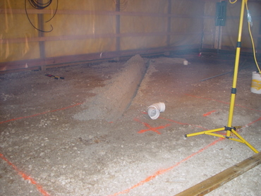
Site preparation for this type of construction is absolutely critical. Builders refer to this as creating a pad on which the building will sit. I hired an excavator to come in with a bobcat and strip the topsoil down 12 inches, then haul in 12 inches of gravel and level the gravel perfectly. The gravel extended about 2 feet past the 30 by 40 foot perimeter giving the construction crew a flat and level pad on which to construct the building. The site preparation work was not cheap, but had it not been done, I would not have been as happy with the outcome. The next major consideration was how I was going to heat my shop. I have suffered through many a cold northern Illinois winter in my old “chicken coop” workshop. I used various kerosene heaters that took the chill off, but were by no means satisfactory. I wanted to plan a heating system for my new shop that would make it comfortable to be in it during the winter months. I researched the many options most of which involved some kind of forced air heating. I have a friend with a similar shop who had radiant floor heating installed directly in the concrete. That proved ideal for a workshop but on talking to him about what it cost, it seemed to be way too expensive. Then I discovered a company on the Internet called Radiant Floor Company out of Barton Vermont. I figured a company in Vermont selling heating products must know what they’re talking about! Their web site http://www.radiantcompany.com/ is a goldmine of information. With help from their expert staff, I was able to design a radiant floor heating system for my shop that has proven to be wonderful. It also turned out that if I was willing to do all the work myself, the cost of materials was compatible with other types of heating systems.
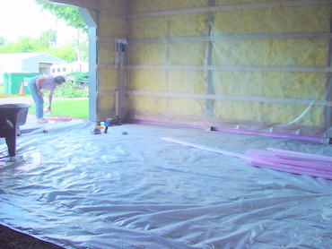
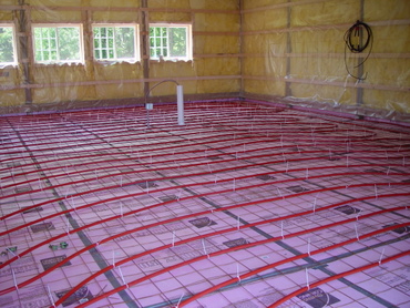
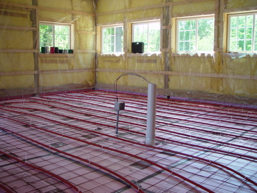
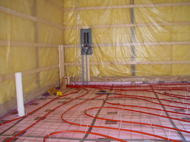
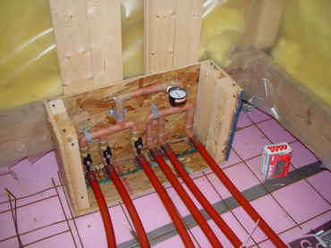
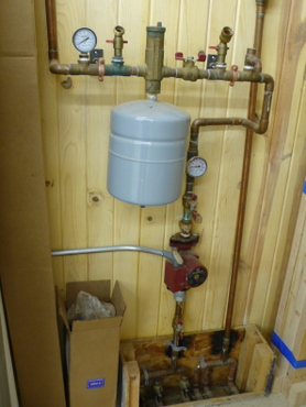
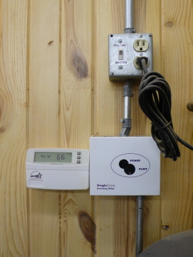
Radiant floor heating uses PEX tubing buried directly in the concrete. Heated water is pumped through the tubing which heats the concrete, which in turn, heats not only the shop, but all the tools sitting on the concrete floor. This means that the floor and all the tools become part of the heating system, all acting as a large heat sink so to speak. My particular design called for 900 feet of tubing run in three 300 foot loops. The water is heated with a common hot water heater and is pumped with a standard pump commonly used in water heated systems. I learned that the trick to installing the tubing was to figure out a way to assure that the tubing was not compromised during the concrete pour. This is a simple matter of presurizing the tubing system with 50 pounds of air pressure and watch carefully to be sure that the pressure does not drop as the pour progresses. Sounds good, but believe it or not, I had to be out of town on business trip the day the concrete floor was poured. Fortunately for me, I was working with a highly experienced concrete contractor who had poured many other radiant floor jobs, so he was very familiar with keeping an eye on the pressure during the pour. One of the lessons I learned during this entire process was how critical it was to choose contractors who really know what they are doing. Believe me, it is worth paying more to get someone working on your project that has done what you want done many times in the past.
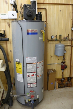
Initially the heating system is charged with only water, but a few weeks prior to the first heating system, I replaced about half the water with specially designed antifreeze. That way I do not have to worry if I ever loose power for an extended period during the winter months, or if I simply want to leave during the winter and turn off the system. The antifreeze I used is good to 50 below zero. The entire heating system is driven by a standard 50 gallon hot water heater burning propane fuel. It may seem surprising that you can heat a 1200 square foot building with a standard hot water heater, but I can assure you that if the building is properly insulated, the system performs wonderfully. During cold January days when the sun is shining in through the south facing windows, the heating system does not run and the shop temprature slowly rises throughout the day. In fact, the system has proven so effecient that even on cloudy days I seldom hear the system cycle.
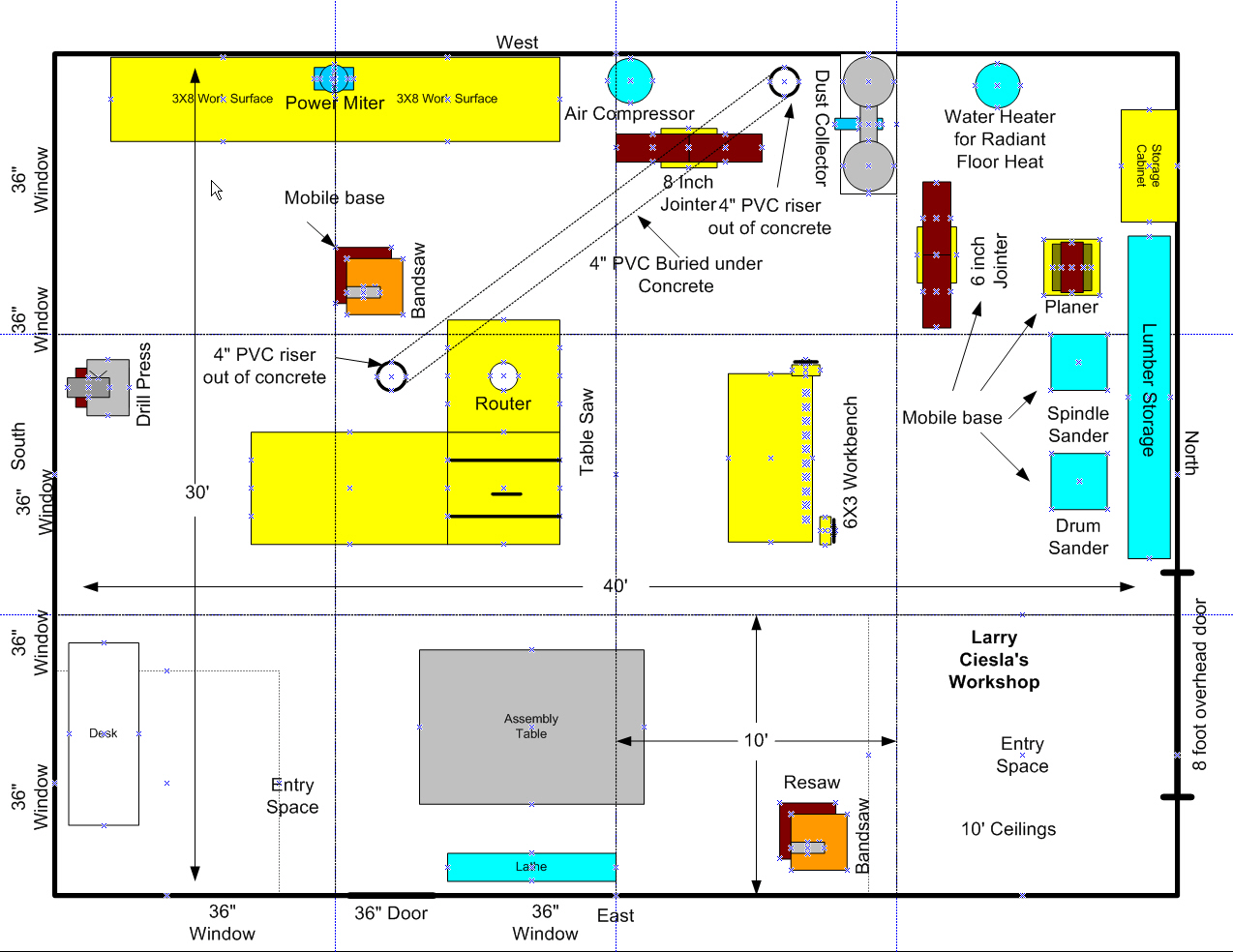
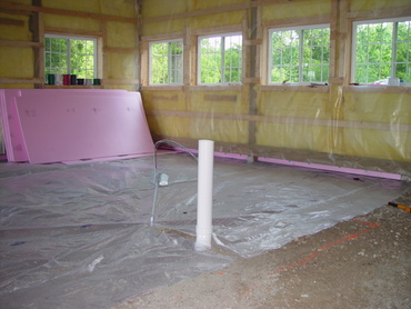
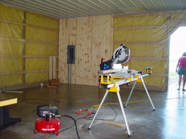
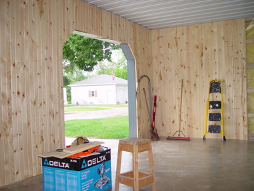
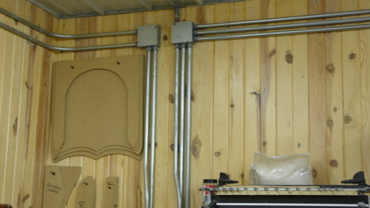
I mentioned earlier that prior to the concrete pour was my chance to run any under-concrete electrical conduit and dust collection. I decided that the table saw and band saw would be more or less in the center of the shop, and based on my scale drawings, I had a pretty good idea of where these tools would live. I needed to supply both 120 and 220 VAC power to this cluster as well as provide underground access for dust collection. Running the power under the concrete is simple enough and it is easy to find plastic conduit specifically designed for this purpose. Dust collection, however, is an entirely different matter. I was unable to find any underground dust collection piping specifically designed for this purpose, so my only choice was to use standard 4 inch PVC pipe. Using PVC piping for dust collection remains a very controversial topic among woodworkers. There are those who say that doing so incurs the risk of a spark in the pipe catching the dust on fire. Frankly, I have a difficult time believing that is a real risk since the PVC pipe is a nearly perfect insulator and building up enough electrical charge on the surface of the interior of the plastic pipe seems impossible. I can also tell you that after nearly five years of use, I have had absolutely no issues with this approach. After the concrete floor was poured, the next step was to rough-in enough of the electrical system so I had enough power in the shop to run a few power tools. The next step in the process was to cover the walls and one of the major decisions I made was to cover all the walls with wooden “car siding.” This is typically knotty pine with tongue and groove and was originally designed to line the walls of rail freight cars. I really like this look and reasoned that having every wall made entirely out of wood, I would be able to use screws to mount nearly anything nearly anywhere. Again, after nearly five years using the shop, this has proved to be a very good decision and I would not hesitate to advise anyone to do something similar. As a side note, finding enough material to cover all the walls of a 1200 square foot building at 10 foot ceiling heights proved to be somewhat difficult. I managed to use nearly every decent piece of material available at the four closest Menards stores!
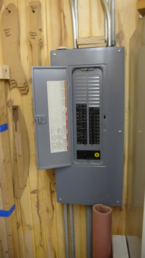
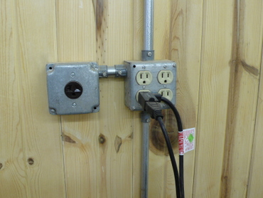
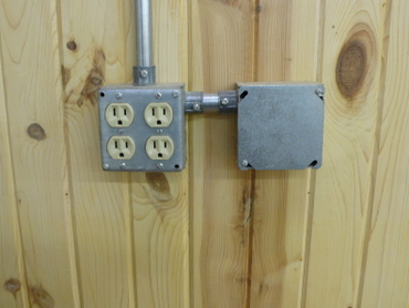
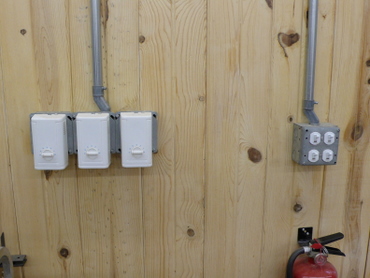
I happen to be an electrical engineer, so I was bound and determined that this shop would have enough power to assure that I would never have any problems, and would be able to allow several major tools to be operated at the same time. My first and foremost concern was safety. Very few woodworkers, unless they happen to also be electrical engineers, know anything about how to safely wire a workshop. There are two related concerns: capacity and safety. Capacity means that you have wired the shop correctly so every circuit has ample capacity to handle whatever load you present. Safety is a really big deal when you realize that many woodworking machines are made from steel and the only thing separating you from instant death are the safety measures built into the tools and the system used to wire the shop. Grounding is the single most critical aspect of correctly wiring a workshop and I have written a separate article dedicated to attempting to explain (in layman’s terms) how grounding works and how it can save your life. In simple terms, I wanted to be absolutely sure that the green ground was carried electrically to every single outlet. Normally, the conduit is used to electrically connect each outlet to the earth ground. I have seen, however, the physical connection from a piece of conduit to a connector fail leaving the outlet at risk. To avoid that, I went the “extra mile” to carry a “green wire” ground to every outlet and to bond that outlet physically to the green wire. In essence, this is definitely a “belt and suspenders” approach to safety, but I’ve always believe that if something is worth doing, it is worth over doing. The other major consideration when wiring the shop is to be sure that you provide ample separate circuits so the probability that any single circuit will rarely, if ever, support more than a single operating power tool. In simple terms, I used to 200 Amp service panel to give me lots of places to place individual circuit breakers, and I was very careful to be sure that any given circuit breaker would serve at most two outlets. That way, each outlet is essentially on its own circuit, and it is very easy to plug another tool into a close by outlet that puts it on its own circuit. The other way to “overkill” shop wiring is to use a wire size one gauge higher than what might be called for strictly by code. For example, most home circuits are wired with 14 gauge wire that is rated to support 15 amps of current to all the outlets on that circuit. I chose to use 12 gauge wire (which supports 20 amps of current) for all 110 VAC outlets, and then I was very careful to be sure that no more than two outlets would be on any given circuit. I used a bit more wire, and that wire was slightly more expensive, but I have absolutely no problem running many tools at the same time. I also wanted to assure that I would have a lot of flexibility on where I installed any tools that required 220 VAC. I knew that my table saw, dust collector, and jointer would require 220 VAC, but I was not sure how many more tools I would purchase in the future that would need 220 VAC. So, I used the same philosophy for 220 VAC by taking advantage of the ample number of spots to place breakers in the 200 AMP service panel. In total, I provided eight 220 VAC circuits, three of which I had an immediate use for, and the remaining five for future use. In the years since I built the shop, I added three more tools needing 220 VAC, and I was very happy that I provided an ample number of circuits. One final thing I would add to this discussion is that you should not attempt to do this yourself unless you know and understand exactly what your are doing. Even as an electrical engineer, I did not hesitate to consult the local electrical building inspector before I did anything electrical even remotely related to safety. Most of the U.S. electrical code exists for the sole purpose of keeping us alive using electricity in our daily lives. The electrical code is complex, obscure, and difficult even for an electrical engineer to understand, so do not hesitate to plan on spending serious money to pay an electrical contractor to handle this aspect of shop construction for you. What you can and should do, however, and become knowledgeable enough to tell your contractor exactly what you want. Do not let him talk you out of lots of individual circuits and bonding the safety ground to every metal outlet!
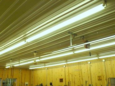
Shop lighting is another major concern designing your workshop. I was 55 years old when I began this project and reasoned that I would only get older as time went on, and everyone knows that as we age our vision gets worse. I chose to use fluorescent lighting and chose eight foot fixtures. I divided the shop into four lighting zones along the length of the shop. Each zone is served by four eight foot duplex fluorescent fixtures each having two 100 watt bulbs. Doing the math, that is thirty two 8 foot 100 watt fluorescent light bulbs! You may be thinking “this guy is nuts,” but again, this has proved to be a decision I would absolutely not change in any way. Each of the four lighting zones is on a separate circuit and each is controlled by its own switch, so I can selectively light the area of the shop I’m working in. About the only time I use all four zones at the same time is at night.
|