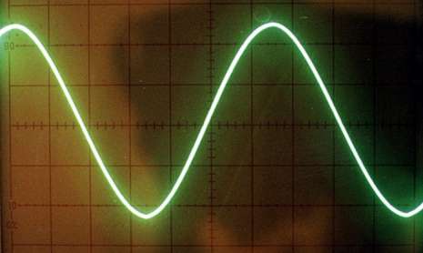
Understand Proper Grounding for the WorkshopThis is an article I've preprared for possible submission to a woodworking magazine:Understanding proper grounding in the woodworking shop requires a basic understanding of a few important electrical engineering concepts. I’ll limit this discussion to only those concepts that directly pertain to our discussion on safety grounding. Electrical power is distributed to residential customers as alternating current, or AC. Alternating current is produced by the alternating voltage generated by the power company. Alternating voltage is not constant or steady like a battery, but rather alternating in what is called a sine wave.
If you measure the amplitude of a sine wave at any given instant in time it will have a certain value. The peak value is referred to as the amplitude which repeats at a certain frequency. In electricity, the amplitude of the waveform is measured in Volts. The waveform is characterized in terms of cycles per second, or Hertz. The power in the typical American home is 60 cycles per second, or 60 Hertz, and the amplitude or voltage is approximately 120 Volts Alternating Current, or 120 VAC. Most power tools in the workshop are designed to work off 120 VAC, but some heavy duty tools or machines are designed to work off 240 VAC. The power distribution system in your home is designed so that either voltage is available at the power panel allowing your electrician to wire the circuit according to the type of power required at the outlet. So far, I’ve talked about voltage and said that the amplitude or maximum value of the voltage in your home alternates and reaches a maximum value of 120 Volts. But what exactly is a volt? A volt is simply a measure of the potential difference or electromotive force between the lowest and the highest value. In the diagram above, the lowest value is zero and the highest value is 120 Volts. For electricity to do work for us, the voltage or electromotive force causes electrons to move through wires connected to a load. The word “load” refers to the thing the work is being done to, say an electric motor. This is not much different than a water tower that stores thousands of gallons of water in a tank high off the ground. Gravity causes the water to flow through pipes into your sink. In much the same way, the electromotive force causes electrons to flow through the wires connected to the load. The rate at which electrons move through the wire is measured in units called Amps. The amount of resistance to the flow of electrons through the load is measured in units called Ohms. Resistance is similar to the diameter of the pipe carrying the water from the water tower to your home. The larger the diameter of the pipe, the more water it can carry per unit of time, or the lower its resistance to the flow of water through it. The narrower the pipe, the higher its the resistance to the flow of water. Electrical wires and electrical loads act in a similar way. Very thick wire is able to carry very high Amps without overheating. Very thin wire can carry only a small electrical current before overheating. Electrical loads that have low Ohms allow electric current to flow more freely than loads that have high Ohms. Using the water pipe analogy, imagine a very large diameter water pipe is connected to a valve. If the valve is totally open, it provides the minimum amount of resistance to the flow of water. If the valve is half open, the resistance to the flow of water is increased. When the valve is completely closed, its resistance to the flow of water is infinite. You can think of electrical loads like motors or light bulbs in a similar way. They allow electric current to pass through them, but unlike a wire, they are not a perfect conductor and present a certain amount of resistance to the flow of electric current. The amount of
power produced by the electromotive force pushing electrons through a load is
measured in “Ohms Law” was the first equation I learned when I was studying to become an electrical engineer. Ohm’s law represents the fundamental relationships between voltage, current, and resistance, and is: E = IR or voltage (E) is equal to electrical current (I) measured in Amps times resistance (R) measured in Ohms. With algebraic manipulation, we can solve the equation for electric current: I = E/R Put in words, the electrical current in Amps (I) is directly related to the number of volts (E), and inversely related to the resistance (R) to the flow of electrons. Here is a very simple electrical schematic showing a 120 VAC power source, a 15 Amp circuit breaker, and an electrical load that has 10 ohms of resistance.
There are a couple of important points to note about this schematic. First, notice that electrical current flows out one side of the 120 VAC source through the load and back into the other side of the voltage source. Second, the circuit breaker provides a path for the electrons to flow through and acts like a piece of wire. It will continue to do so as long as the electrical current passing through it does not exceed its rating in Amps. Using the equation I = E/R we can calculate that the amount of current flowing in this circuit is 120 Volts / 10 Ohms, or 12 Amps. Notice that as the resistance of the load goes down the Amps goes up. So 5 Ohms would result in 24 Amps, 1 Ohm 120 Amps, and so on. Of course, the circuit breaker would open and stop the flow of electrons as soon as the load drew 15 or more amps from the source. The most extreme example is to imagine replacing the load with a straight piece of wire where the resistance is nearly zero. If you would do so, the resistance to the flow of electricity in the circuit would be very nearly zero which, according to Ohms law, would result in an infinite amount of current flowing through the circuit. You will soon see how this fact is critical to how proper grounding protects you in the workshop. Your power company uses a sophisticated power distribution network to deliver electrical power to your home and shop. If you look carefully at the major power distribution lines that deliver electrical power to thousands of homes and businesses, you will notice that the electrical wires that carry all this power are remarkably thin. How can such thin wires carry electrical power to all those homes? The power company takes advantage of the second fundamental equation describing the relationship between voltage (E) and current (I) that yields power (P): P = EI or Power is equal to voltage (E) multiplied times current (I). Going back to our simple circuit, we can use this equation to calculate the amount of power being delivered to the load:
Ohm’s law tells us that the electrical current flowing in this circuit would be 120V / 10 Ohms or 12 Amps. We can use the equation P = EI to calculate that the load is consuming 120V times 12 Amps, or 1440 watts of power. Notice that 240V * 6 Amps will also deliver 1440 watts of power, as will 480V * 3 Amps, 960V * 1.5 Amps, and so on. This means that the higher the voltage, the fewer the Amps needed to deliver the same amount of power. The power company makes extensive use of this fact to design their power distribution system. They carry and deliver tremendous power by using transformers to step up the voltage to extremely high values. As the power lines get closer to the ultimate destination, they step this voltage down to lower levels. In my neighborhood, the power company distributes power to homes by providing 7200 Volts on a pair of wires carried on a power pole. But 7200 volts is still far too high a voltage to bring into my home, so a final step down transformer is used to drop this voltage down to 240 volts. All transformers work on the principle that electricity and magnetism are different forms of the same thing. This was one of the more difficult concepts I had to grasp as an engineering student, but the basic idea is to use two coils of wire separated electrically but connected magnetically. One side of the transformer is called the primary and the other side the secondary. The voltage out the secondary is either stepped up or stepped down by the ratio of the turns of wire in the primary and secondary coils. The final step down transformer that delivers power to my home has a center tap that is very important to our discussion of proper grounding in the shop.
If you measure the voltage across the entire secondary of the transformer, you will measure 240 Volts. If you measure the voltage from the center tap to either side of the secondary, you will measure 120 Volts. Now, it turns out that the atmosphere we breathe and the earth upon which we walk are both conductors of electricity. Just look outside during a thunderstorm and observe lightning. Lightning travels through the atmosphere from an area in the clouds where a large amount of electrical charge (e.g.: electrons) have built up to another point either in the atmosphere or on the earth were few electrons exist. Nature is trying to reach an equilibrium where charge is distributed everywhere evenly. When this distribution gets out of balance, electrons will flow from a point with a high concentration to one with a low concentration. There are many reasons why the power company uses the concept of a ground and one of them is to protect the system as much as possible from lightning strikes. But the concept of connecting the system to ground also provides many other critical safety benefits. The concept of a ground is very straightforward. The power company will bury a long copper rod near the power pole and connect the center tap of the transformer to the earth.
Connecting the center tap to the earth does not change any of the voltage measurements, but does add another electrical reference from which we can make the measurements – the earth itself. Even though the earth is a conductor of electricity, the fact that the center tap is connected to the earth does not mean that any electrical current will flow through that connection. In fact, this electrical path to the earth only comes into play when something goes wrong. For example, if lightning were to strike the transformer on the power pole, since the transformer is connected directly to the earth, the lightning will be channeled to the earth by this connection. Electricity always takes the path of least resistance, and the connection to the earth is an easier path for it to take than to travel along the wires into your home which itself is sitting upon the earth. Electrical engineers learned long ago that this connection to the earth provides many other safety benefits. This learning is reflected in the National Electrical Code which contains a hundred years of collective wisdom about how to make electrical systems safe for humans to use. Much of the code is devoted to rules that carefully define how systems that consume power should be properly grounded to afford the maximum amount of protection. In the remainder of this article, I’ll attempt to explain how grounding provides this protection. I will not, however, tell you how to apply the electrical code to your specific situation. That is something only a fully qualified electrician or electrical engineer should do. Modern homes are equipped with a power distribution panel. The purpose of this panel is to provide a termination for the wires from the power company into your home allowing you to safely tap into the power and distribute it to various points in your home. Most home power distribution panels utilize circuit breakers to limit the amount of electrical current that can flow into the home itself, or into any of the individual circuits coming from the power distribution panel. Power panels are typically rated by the number of amps of electric current they can safely distribute. Most homes will have either a 100 Amp or 200 Amp power distribution panel. If you visit a home center and look carefully at a typical power panel, you will notice that the power panel is designed to mirror the power as it leaves the power company’s transformer. The center tap of the transformer will be connected to the grounding bar in the power panel, and each of the other two wires will be connected distribution assemblies where you can install individual circuit breakers for each 120 VAC or 240 VAC circuits you need in your home.
The wire from the transformer’s center tap that was connected by the power company to the earth ground gets a second connection to earth ground at your power distribution panel. This can be accomplished either by running a heavy copper wire from the grounding strip in the panel to a copper ground rod buried just outside your home, or in some cases by connecting to a metal water pipe in your home. This may seem like a belt and suspenders approach to grounding since the distance from the transformer on the power pole to your home may not be very far, but this ground connection is so critical to your safety that it not worth relying on only one connection. The metal box housing the power distribution equipment is electrically “bonded” to the ground connection. If metallic conduit is used in your home or shop to carry wires to outlets, the conduit and the metal outlet boxes will be grounded as well. If non-metallic cable is used instead, an un-insulated wire is always buried in the plastic sheathing to carry the ground to the outlets. In the discussion that follows, I’ll be assuming that conduit is being used, but the principles are exactly the same for non-metallic cable. This un-insulated wire and the green wire I’ll be describing both serve the same purpose. To make it easy to identify the purpose of wires in your home, a color code convention has been widely used for many years. Each circuit will have at least two wires. 120 VAC circuits have a black wire (sometimes called the “hot” wire) and a white wire often referred to as the “neutral” wire. For extra safety, a green wire is used to directly connect electrical outlets to the neutral bar in the power distribution panel. I’ll be talking a lot about this green wire a bit later when I explain how proper grounding protects you in the event of failure. The diagram below is an electrical schematic of a simple home distribution panel with one 15 Amp 120 VAC circuit.
This diagram shows the electrical connections to a typical outlet to provide 120 VAC. Notice that the wiring is run from the power distribution panel to the outlet through metallic conduit that is physically and electrically connected to the distribution panel. By convention, the black wire is connected from the circuit breaker to the shorter prong of the plug. The white wire is connected from the neutral bar to the longer prong of the plug. For safety, a third green wire is shown connected from the neutral bar to the ground prong on the plug. It may seem strange that the conduit, the metal box housing the plug, the white wire, and the green wire are all connected to essentially the same place – electrical ground. But this arrangement has proven to provide the maximum amount of safety and I’ll explain why now. The body of your
table saw is made out of steel and is an excellent conductor of
electricity. The motor that drives the saw
blade is also made of metal and is physically attached to the saw body. For the motor to operate, it must be
furnished with electrical power delivered to the motor via insulated
wires. Those insulated wires must pass
through a hole in the metal body of the motor and be connected to the internal
connectors of the motor. It is important
to understand that the internal circuitry of the motor is normally electrically
isolated from the metallic body of the motor.
When you operate your table saw, you will be standing on the ground and
will be touching the metal body of the saw.
We’ve seen that the electrical system providing power has one side
connected to the same ground you are standing upon, so if something goes wrong,
electrical current could use your body as a path to ground. This will probably only happen once in your
lifetime because the chances are very good that your life will end if that
happens. But a properly grounded system
will protect you if a failure in the insulation occurred causing the black wire
to contact the metal body of the motor. Here
is a simple schematic that shows a motor connected to AC power. Notice that the black and white wires are insulated and pass through the metal body of the motor. Because the wires are insulated, the wires are isolated from the metal body of the motor and the motor and anything else it touches is electrically neutral. Suppose a failure occurs in the insulation of the white wire causing the white wire to contact the metal case.
This particular failure is causing the metal motor case to be electrically connected to the white wire, but we are very lucky because this particular failure is totally harmless. The reason why it is harmless is because the metal body has shorted out to the white wire which is electrically at the same potential as ground. When we touch the saw, nothing happens because the saw body is still at the same potential as the ground. But what would happen if the failure occurred in the black wire instead of the white wire?
Now we are in big trouble because when we touch the metal saw body, it will be at the same electrical potential as the black wire. As soon as we touch the saw, we place our body in parallel with the saw motor and are exposed to 120 VAC of electricity. If, however, the outlet the saw is plugged into has been wired correctly, the green wire comes into play to save our life! By convention, the green wire or safety ground is always connected to the body of the device under power. In this case, the green wire from the plug will be physically attached to the body of the table saw thus ensuring that the saw body will be electrically grounded.
Because the body of the saw and the body of the motor are both grounded, the insulation failure of the black wire causes a short circuit to occur that immediately blows the circuit breaker. Electrically, the effect of connecting the green wire to the body of the saw looks like this:
The green wire introduces a short to ground with zero ohms of resistance. If you recall the formula for calculating electrical current in a circuit, we said that I = E/R. If R = 0 (a short) then I = E/0 and any number divided by zero equals infinity. So the green wire will effectively try to draw an infinite amount of electrical current through the circuit breaker. The circuit breaker is designed to trip as soon as a certain amount of electrical current is exceeded, typically 15, 20, or 30 Amps. For all intents and purposes the breaker will trip the instant the black wire touches the metal body of the motor, opening the connection to the black wire. Even were you to be touching the metal body of the saw at the very instant that the black wire touched the metal body of the motor, you would still be protected because the body of the saw itself is attached to the same ground on which you are standing. The principle is the same if your table saw is wired for 240 VAC, but electrically things look a bit different.
The circuit breaker in the power distribution panel that delivers power to a 240 VAC circuit actually spans both sides of the power company’s transformer. Unlike a 120 VAC circuit breaker that uses the grounded center tap as the electrical reference, a 240 VAC circuit connects to the opposite ends of the power company’s transformer effectively ignoring the center tap. By convention, a black wire is connected to one side of the circuit and a red wire is connected to the other side of the circuit. Even though the grounded center tap connection is not used, maintaining a connection to ground is still critical to safety, so the green wire must be connected from the neutral bar and carried along with the red and black wires to the outlet. Notice also that outlets designed to deliver 240 volts are radically different than outlets designed to deliver 120 volts. This is done to prevent someone from accidentally plugging a 120 V appliance into a 240 V outlet. If the correct receptacles are used, it becomes impossible to make this mistake. You will recall from our discussion of 120 VAC circuits earlier that if a failure occurred that caused the white wire to contact the metal case we would not be in danger because the white wire and the green wire and the ground we are standing upon are all electrically neutral. With a 240 VAC circuit, however, if either the red or black wire comes into contact with the metal case we have a potentially deadly situation. Even though the grounded center tap of the transformer is not used in 240 volt circuits, it is still the key to protecting us from failures. To understand how this works, we’ll examine the following schematic of a typical 240 volt circuit:
There are a couple of important things to note about this schematic. First, we see that the connection to ground at the power source is still shown, so if you were to measure voltage from ground to either the red or black wire you would measure 120 VAC. Measuring from the red to the green wire you will see 240 VAC. Second, notice that the 240 VAC circuit breaker actually consists of two sides and that the current exceeding the rating for the breaker from either side will cause the entire breaker to open the circuit. Understanding this is key to understanding how the green wire ground protects us. Now let’s introduce a failure. It really does not matter if the red or green wire’s insulation fails, so we’ll pick the red wire. If the red wire were to fail in such a way that the wire came into contact with the metal body of the motor, our electrical schematic will now look like this.
Electrically, everything changes. Notice that when the red wire touches the metal case, it becomes electrically connected to ground through the green wire. The diagram bellow illustrates the path the current will take on the red side.
If you look closely, you see that from the perspective of the bottom 120 VAC voltage source, there is a dead short across it. This means that the load presented to that half of the power source is zero ohms, and if you recall from Ohm’s law, zero ohms will try to draw an infinite amount of current from the source. After a few microseconds of current buildup, the circuit breaker will sense the rise in current and trip both halves of the circuit breaker and the danger will immediately pass. If, on the other hand, that green wire safety ground were not hooked up, the body of the machine would electrically be the same potential above ground as the red wire, or 120 Volts. Touching the saw under these circumstances would almost certainly be fatal. There is one additional safety device that should be used whenever a circuit could be used to power any device used outdoors. Let’s talk about an electric drill designed to be plugged into a standard 120 VAC circuit. Many drills are designed using a technique called double insulation where the wires are isolated from the external body of the drill, and the body of the drill itself is an insulator. Theoretically, since any metal on the drill is double insulated, there should be no way your hand could come into contact with the hot wire. A double failure of some sort would have to occur and the chances of this happening are very small. Unless, that is, the drill body comes into contact with moisture. It turns out that water is a good conductor of electricity, and a coating of moisture on and through the drill from leaving it out overnight might provide enough of an electrical path to your hand to be very dangerous. Since the drill body is an insulator, connecting the green wire safety ground to the drill body does not protect you in the same way as it did with your table saw. To understand how we can protect ourselves from this type of failure, we have to learn more fundamentals of electrical engineering.
Here is a circuit drawing that shows the electric drill motor having an equivalent resistance of 60 Ohms. Recall from Ohm’s law that I = E/R, so the current flowing in and out of the motor is 120 VAC / 60 Ohms = 2 Amps. It is important to understand that two Amps of current will flow through the black wire through the motor and exactly two Amps of current will flow back through the white wire. The green wire, since it is attached to exposed metal which is electrically insulated, will carry no current. All the current will flow through the black and white wires and be exactly equal. Now, let’s imagine that the drill has sat out overnight and a coating of moisture has formed on the plastic body, and some moisture has also found its way into the motor itself and is in contact with the exposed metal contacts from the black wire to the motor. Now the electrical characteristics of the circuit have changed. The body of the drill is no longer a perfect insulator, but it is not a perfect conductor either. A perfect conductor will present zero ohms of resistance to the flow of electricity, and a perfect insulator will present infinite ohms of resistance to the flow of electricity. The body of the drill coated with moisture presents some value between zero ohms and infinite ohms of resistance to the flow of electricity. We will not worry about the exact value for now, but will represent this new path from the black wire to the case by a resistor as shown below:
The human body is loaded with water and is itself a conductor of electricity. When we hold the drill in our hand, our circuit changes again and now looks something like this:
Your life now depends upon ohms law! Whether you live or die depends upon the amount of resistance the moisture on the plastic represents. The combination of that resistance plus the resistance in your body (which is standing upon the ground) forms an alternate path for electrical current to take from the black wire, through you and the ground, back to the power source. The greater the amount of moisture, the lower the resistance of the plastic case, the more likely your body will look like just another electrical load to the 120 VAC power source. It will happily deliver I = E/R to your body where R is the sum of the resistance represented by the moisture on and in the drill, plus the resistance of your body. It takes only a very tiny amount of electric current flowing through your heart to cause it to fibrillate. While it takes several amps to operate the electric drill, it only takes 0.006 to 0.2 amps, or 6 to 200 milliamps through your heart for one to three seconds to cause death. Turning back to Ohm’s law, we can solve the equation for R and find that R = E/I, so 20,000 combined ohms will result in .006 Amps, and 600 ohms will deliver 200 milliamps through your heart. If the total resistance is greater than 20,000 ohms, you may escape death but will still receive a nasty shock. If the total resistance is less than 20,000 ohms, it is very likely that you will die. This same principle applies inside the home as well as outside the home. Anytime electricity and moisture can come together we must contend with a special hazard and utilize a different strategy to protect ourselves. That strategy is to employ a GFI or Ground Fault Interrupter type outlet anyplace where you might plug in anything that could possibly be exposed to moisture. The GFI circuitry works on a very simple principle that you should now be able to easily understand.
A GFI circuit works on the principle that the electrical current out of the black wire must exactly match the electrical current in from the white wire. A GFI circuit, like a transformer, takes advantage of the relationship between electricity and magnetism. A small coil of wire is placed around the black wire, and a second small coil placed around the white wire. Both coils are connected to a GFI Sensing Circuit. When electric current passes through the black wire through the load and back into the white wire, that current induces a magnetic field around the wires. The small coils pick up this magnetic field which induces a tiny electric current through the small coils into the GFI sensing circuit. The GFI sensing circuit measures these tiny currents and compares them to each other. If the GFI circuit detects any imbalance in these tiny currents, it will trip the circuit breaker disconnecting the black wire in about 10 milliseconds (0.010 seconds.) This is quick enough that, while you may still feel a shock, it will not last anywhere long enough to cause your heart to fibrillate. A GFI outlet will afford you a tremendous amount of protection, but there is still a failure scenario where it will not be able to protect you. As long as some of the current passes through you into the ground, the GFI can protect you. But if the failure is such that one hand is electrically touching the black wire and the other hand is electrically touching the white wire, the flow of current through the black and white wires will be exactly the same and the GFI will not trip. But this is not likely to happen unless you are intentionally working with these wires exposed and with the device plugged into the power outlet. Electrical engineers can do a lot to make things foolproof, but they cannot make them damn foolproof! Proper grounding in the home and shop is done for one single purpose – safety. Safety around electricity should be taken very seriously because electricity can easily kill. I hope this brief introduction into why grounding in the shop is important will cause you to consult with a licensed electrician if there is any doubt in your mind about if your shop is correctly wired for working with large metal power tools, or with working with tools that can be exposed to moisture. |